A grow room breathes as a system.
Good ventilation is not simply putting a fan in a window. Fresh-air intake, exhaust, carbon filtration, air movement around leaves and moisture removal do different jobs. Start by tracing where air enters and exits, then size the equipment for the room, ductwork and actual conditions.
Exhaust, intake and circulation are not interchangeable.
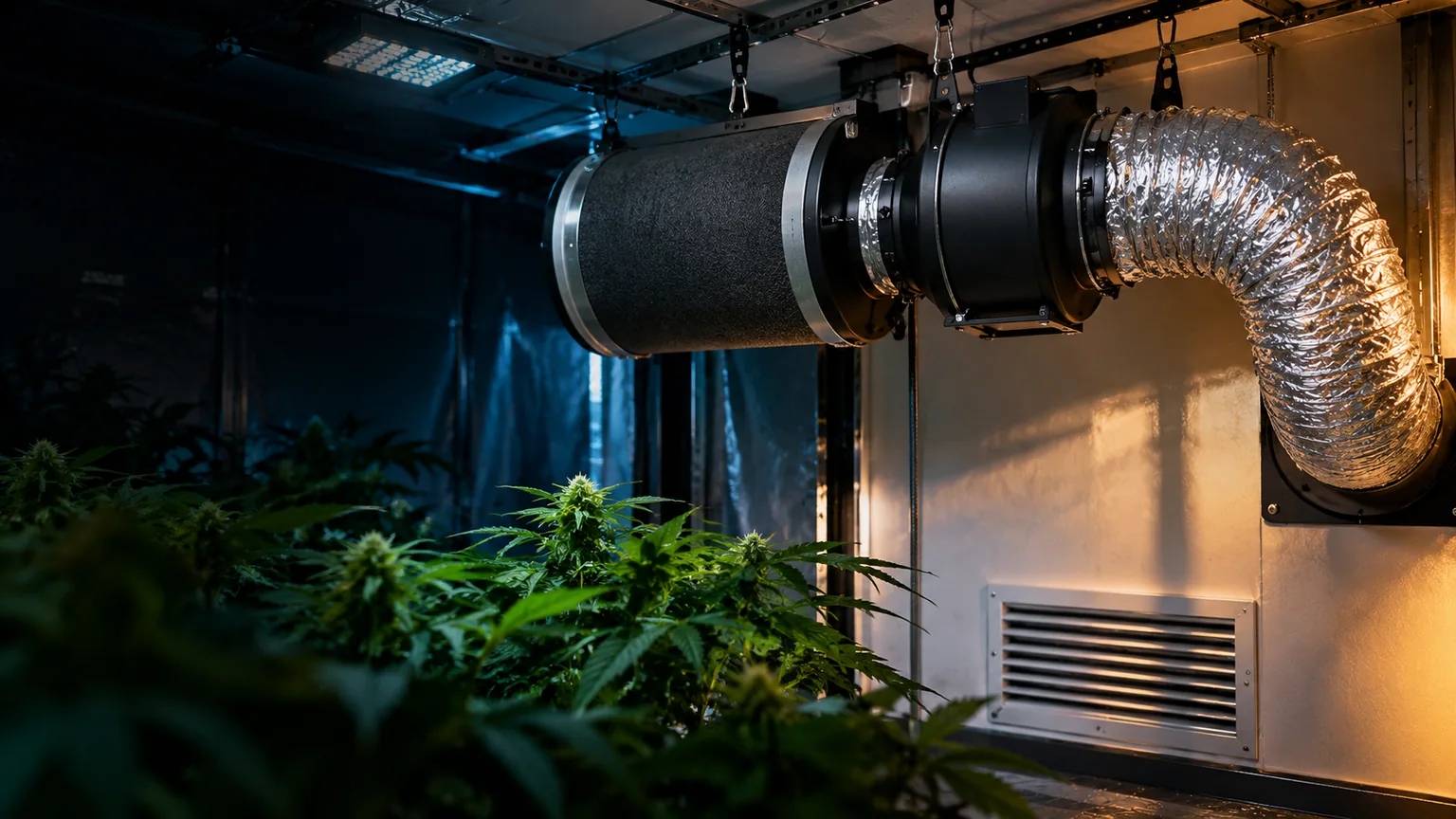
An exhaust fan moves air out of the room. A supply opening or intake fan lets replacement air in. Circulation fans move air within the room so pockets of warm, humid air do not linger around foliage. A carbon filter is for odor control; it does not replace exhaust or dehumidification.
Exhaust
Use a compatible inline or other rated exhaust fan with a deliberate discharge path. Locate the pickup where heat and humidity collect. Duct air to a permitted destination, not into an enclosed attic or another space that cannot handle the moisture.
Replacement air
Provide a suitably sized, unobstructed intake path from a clean source. Many small tents use passive intake. Larger or restricted rooms may require a designed powered supply and appropriate pressure control.
Canopy circulation
Place separate oscillating or circulation fans to move air gently around and through foliage. Avoid an unchanging concentrated blast, cords in wet locations, and dead zones behind dense canopies.
Follow the route, not just the arrows on the fan box.
Keep the exhaust path reasonably short and supported, match duct size to the fan and filter, seal joints, and confirm the fan’s direction. The filter and fan must be compatible with the permitted installation orientation.
Size the fan for the system you actually build.
Airflow is often shown in cubic feet per minute (CFM). As a first planning check, calculate room volume and multiply by a chosen air-change rate. This is not a universal fan prescription or proof that the room’s heat and humidity loads are handled.
A 10 × 10 × 8 ft room is 800 ft³. At an assumed 6 air changes per hour, the arithmetic gives 80 CFM before adding resistance or checking cooling, moisture and outdoor air needs. The required operating flow may be very different.
The rated free-air CFM on a box is not necessarily the delivered flow. Carbon filters, long runs, small ducts, bends, grilles and dampers create static pressure. Consult the fan’s pressure/flow curve and the filter’s rated working airflow. For larger or regulated spaces, have the system evaluated by qualified mechanical/electrical professionals.
Grow Room BuilderEstimate room volume and test different air-change assumptionsVentilation alone is not climate control.
Temperature and moisture
Grow lights, equipment and plant transpiration add heat or water vapor. Exhaust can help when incoming air is cooler or drier, but may be ineffective when outdoor conditions are similar. Measure conditions at canopy height and consider appropriate cooling and dehumidification separately.
Carbon dioxide and plant leaves
Plants exchange gases mainly through stomata. Their opening depends on light, water status and environmental conditions; it is not a reason to rinse plants on an invented schedule. Follow pesticide and miticide product labels, including any restrictions on mixing, washing or post-treatment contact.
Filtration and odor
Activated-carbon filters can adsorb many odor compounds within their rated use conditions. Saturated carbon, bypass leaks and excessive airflow reduce effectiveness. A carbon filter does not scrub every contaminant or make a poorly ventilated room safe.
Air balance
A modest inward tent-wall draw may indicate negative pressure, but excessive suction, obstructed intake or undersized fans can restrict real airflow. Don’t use tent-wall appearance as the only measurement of system performance.
Fire and electrical safety: Use suitably rated fans and outlets. Do not run wet-area extension cords under trays, defeat electrical protections or route ducting against hot lamps and exposed wiring. Any new building penetration, wiring or required exhaust discharge must satisfy applicable codes and permissions.
Inspect the whole path, not just the blades.
- Inspect intakes and prefilters. Remove accumulated dust and verify replacement air has a clear route.
- Check filter condition. Follow the carbon filter maker’s replacement interval and look for odor breakthrough or bypass leaks.
- Inspect the fan and ducts. With equipment safely disconnected, check mounts, vibration, duct kinks and loose clamps.
- Review sensor placement. Keep temperature/RH probes near representative canopy air, away from direct spray or strong fan blasts.
- Verify actual conditions. Compare daytime and night conditions, humidity trends and fan performance rather than assuming a fixed setting stays adequate.
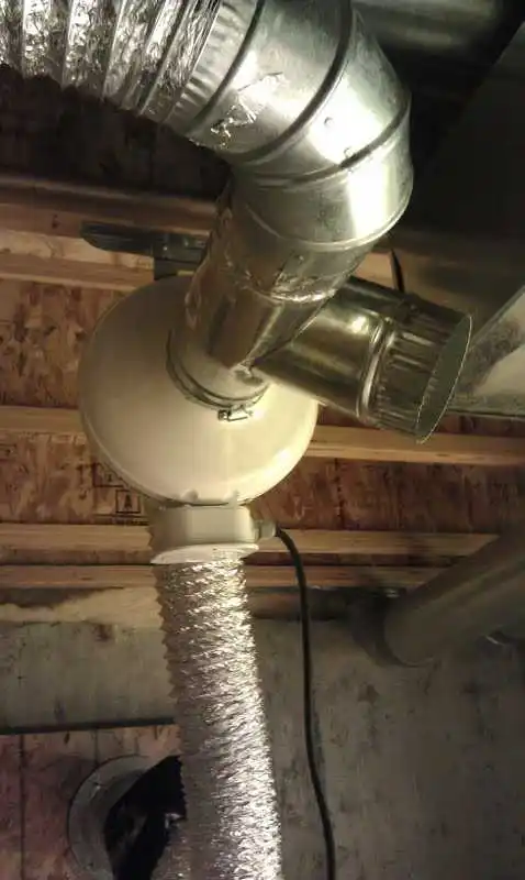
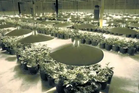
Original ventilation equipment photos
The original photos illustrate legacy fans and ducting. Use current manufacturer instructions and measured room conditions when choosing modern equipment; a photograph cannot establish required airflow or an electrical rating.